02IUT Bordeaux · BUT GEII
Automated loading / unloading station
A robotic station built around a three-axis arm, engineered end to end: from the requirements specification to a commissioned machine with a full operator HMI.
- Arm3 axes
- PLCs2 · master / I-Device
- HMITP700 Comfort
| Role | Automation design, PLC programming, HMI and validation |
|---|---|
| Context | IUT Bordeaux · BUT GEII |
| Stack |
- 01TP700 ComfortWinCC HMI
- 02ET200SPmaster CPU
- 03ProfinetI-Device exchange
- 04S7-1214Cslave CPU
- 053-axis armdrives · sensors
The brief
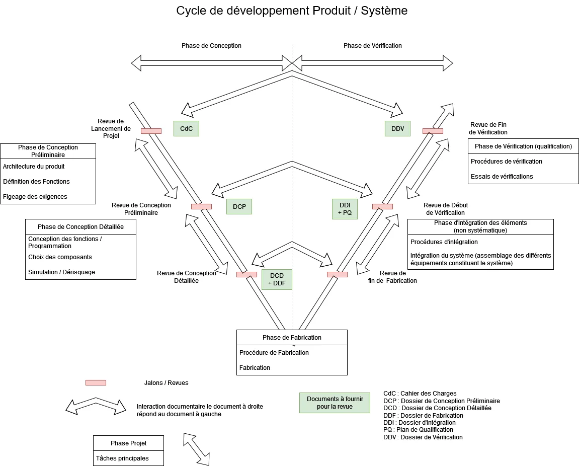
Automate a loading / unloading station built around a three-axis robotic arm. The work followed a V-model process in line with ISO 9001 practice — starting from a written requirements specification and closing with validation against it.
Multi-PLC architecture
Two controllers share the machine over Profinet: an ET200SP CPU as master and an S7-1214C configured as an I-Device slave. Splitting the work this way keeps each program focused and makes the exchange between them explicit and testable.
PLC programming
- Arm trajectories and sequences in TIA Portal.
- GEMMA operating modes: start-up, production, stops, manual and fault handling.
- Safety logic and reusable SCL function blocks.
Simulation before commissioning
Sequences and operating modes were validated in PLCSIM before anything was downloaded to the physical PLC, so commissioning focused on the hardware rather than on logic errors.
Operator HMI
- WinCC on a TP700 Comfort panel.
- Alarm management.
- Recipes.
- User profiles and access rights.
Production context
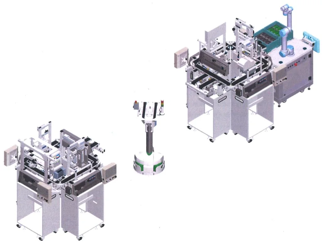
The station sits at the head of a Festo CP Lab Industry 4.0 line that assembles mobile-phone cases. Until then an operator loaded and unloaded the shells by hand; the brief was to integrate a three-axis arm so that the operator could be moved to other tasks.
The line is built from two islands of four stations — storage, front-shell feeding, pneumatic press, drilling, labelling and an outfeed station with a UR5 cobot — linked by conveyors and by a Robotino mobile robot between the islands. Every pallet carries an RFID tag, and the MES sets the route and the parameters written to it.

The machine
| Element | Implementation |
|---|---|
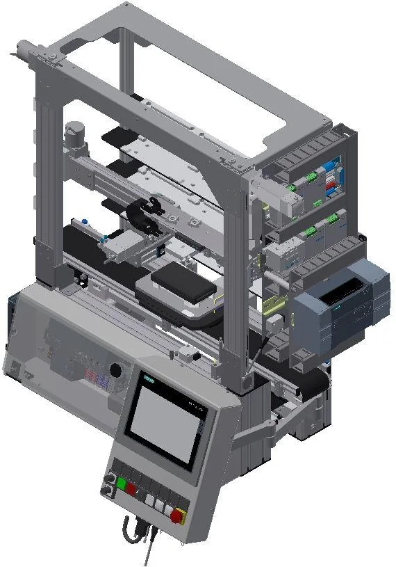
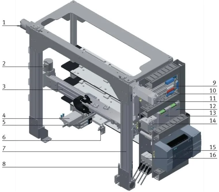
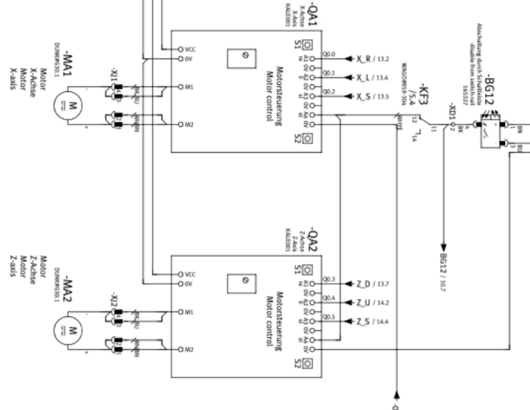
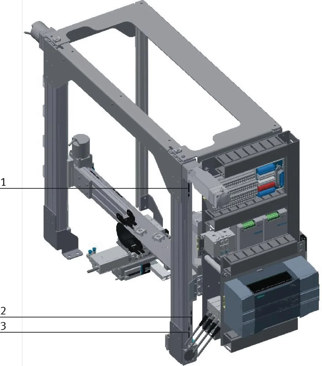
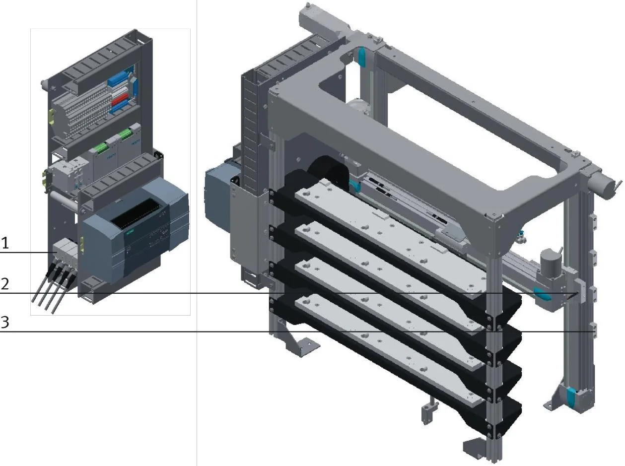
| X axis | Geared motor with right / left / slow-speed commands; incremental quadrature encoder read by a 1214C high-speed counter |
| Z axis | Same arrangement: geared motor, slow speed, encoder on a second high-speed counter |
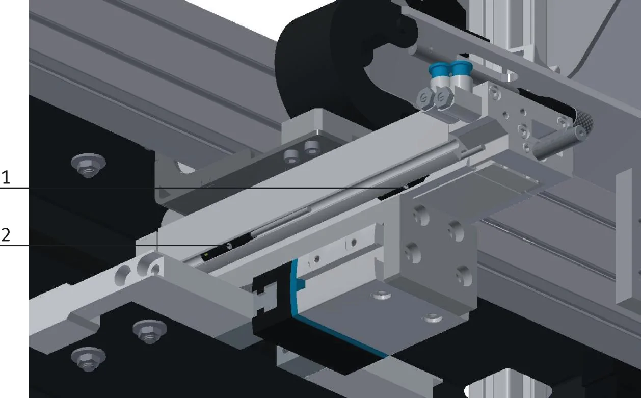
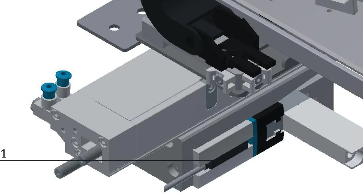
| Y axis | On/off pneumatic cylinder towards the store, with extended and retracted sensors |
| Gripper | Pneumatic, with a closed-state sensor |
| Detection | Fibre-optic sensors for pallet present and shell on pallet; photoelectric sensors for shelf levels and slot occupancy |
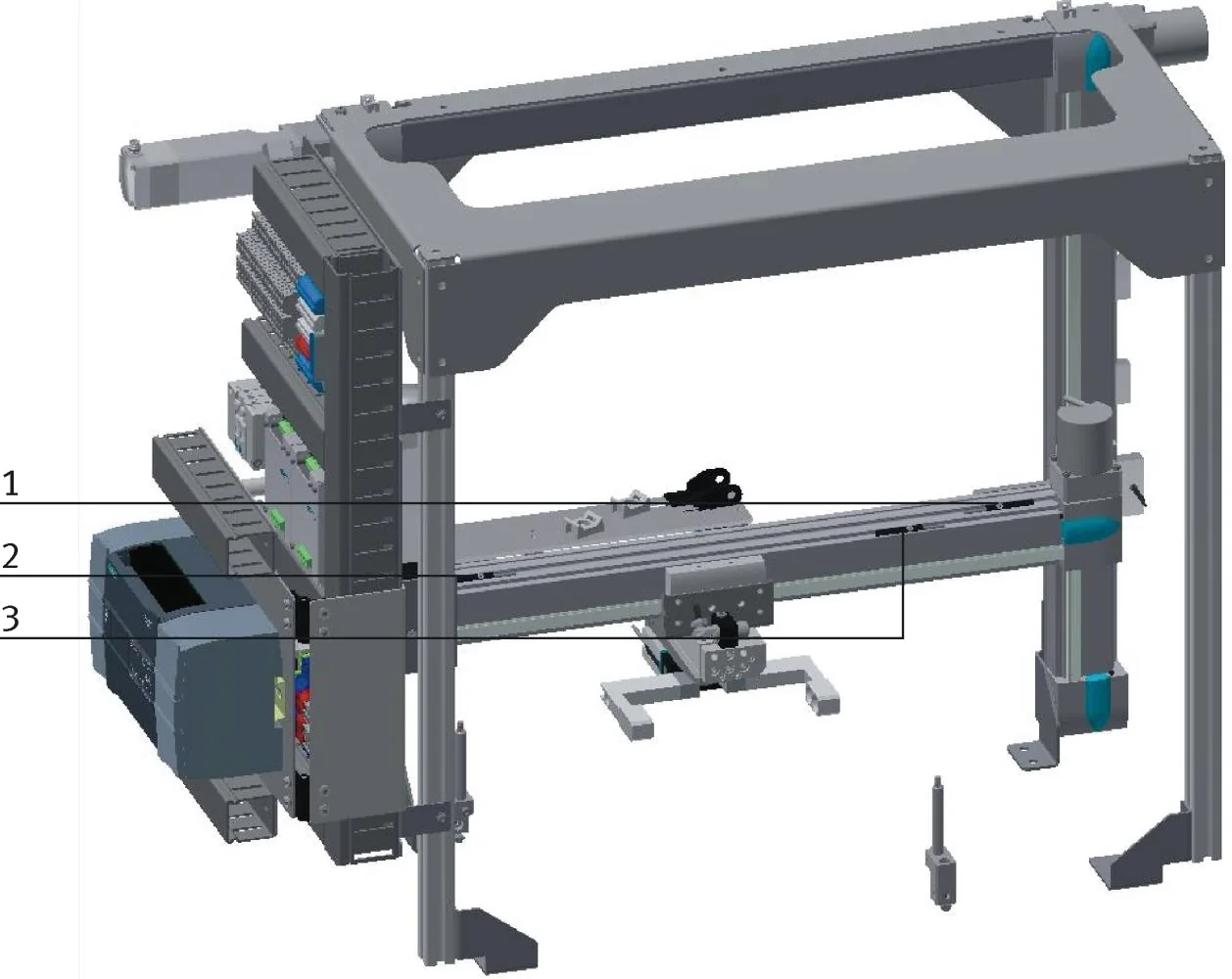
| Travel | Reference sensors on X and Z, end-of-travel sensors on every axis |
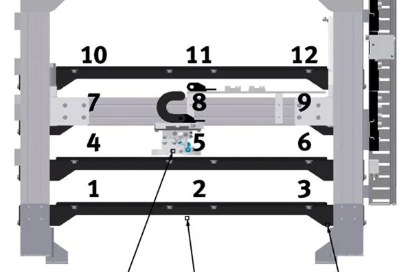
| Store | 12 slots, positions taught in a data block in encoder units |
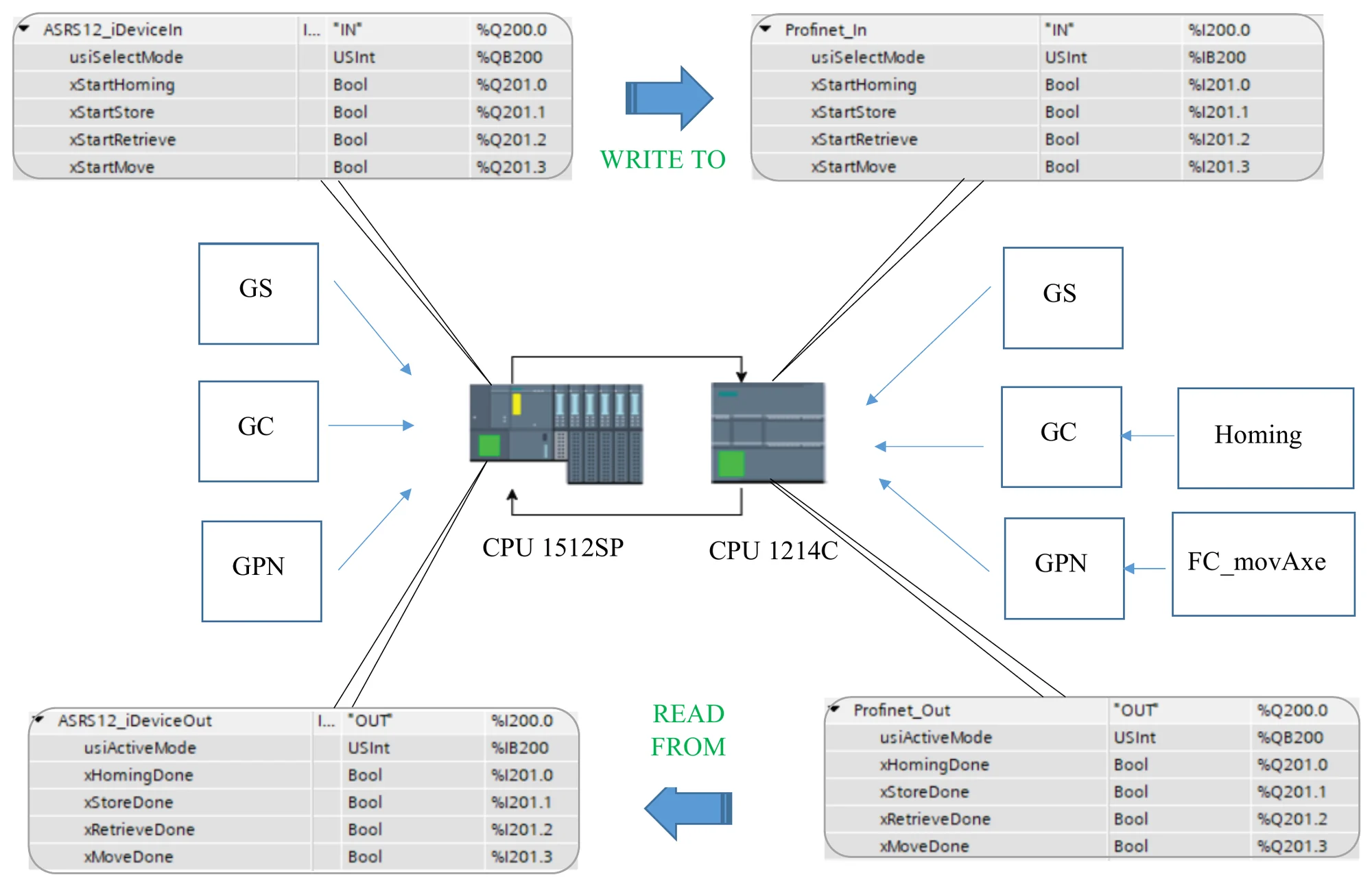
Master / I-Device exchange
The ET200SP CPU 1512SP runs the station — conveyor, control panel, HMI — and sends the requests to the arm. The S7-1214C is declared as an I-Device: the master sees it as an I/O module with two transfer areas, to_ASRS and from_ASRS. The master asks, the 1214C executes the trajectory and reports back.
| Direction | Main signals |
|---|---|
| to_ASRS | Operating mode, start homing / store / retrieve / move, shelf number, X and Z targets and enables, gripper open / close, Y forward / back, workpiece ID |
| from_ASRS | Homing / store / retrieve / move done, current X and Z, gripper and Y states, store full / empty, number of parts in stock, error code |
Axis control
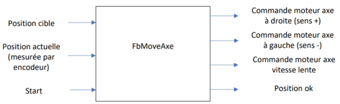
X and Z are positioned by one reusable function block, FbMoveAxe, called once per axis with the encoder count as feedback.
- Direction from the sign of the error between target and current position.
- Slow speed as soon as the error is within ±100 counts, to approach without overshoot.
- Position reached within ±3 counts, which releases the next step of the sequence.
Homing
Incremental encoders lose their count at power-off, so every restart begins with a reference run, triggered by Reset.
- Put the arm in a safe state: Y retracted, gripper open.
- Drive the axes at slow speed onto their reference sensors.
- Stop on the sensor and reset the high-speed counters with CTRL_HSC.
- Move at slow speed to the (300, 300) start position.
Unloading sequence — store to pallet
- Empty pallet detected under the module: move X / Z just above the shell in its slot (Zslot − 10).
- Extend Y into the slot, lower to Zslot and close the gripper (500 ms).
- Lift back to Zslot − 10 and retract Y.
- Travel along X to the pallet, then down along Z to the pallet.
- Open the gripper (500 ms) to place the shell.
- Rise to Zpal − 200 so the pallet can leave, and acknowledge the end of sequence to the master.
Loading sequence — pallet to store
- Pallet carrying a shell detected: move X / Z to the pallet and close the gripper (500 ms).
- Move above the target slot (Zslot − 10) and extend Y into it.
- Lower to Zslot and open the gripper (500 ms).
- Rise to Zslot − 10 and retract Y.
- Wait at Zpal − 200, then acknowledge the end of sequence to the master.
Operating modes
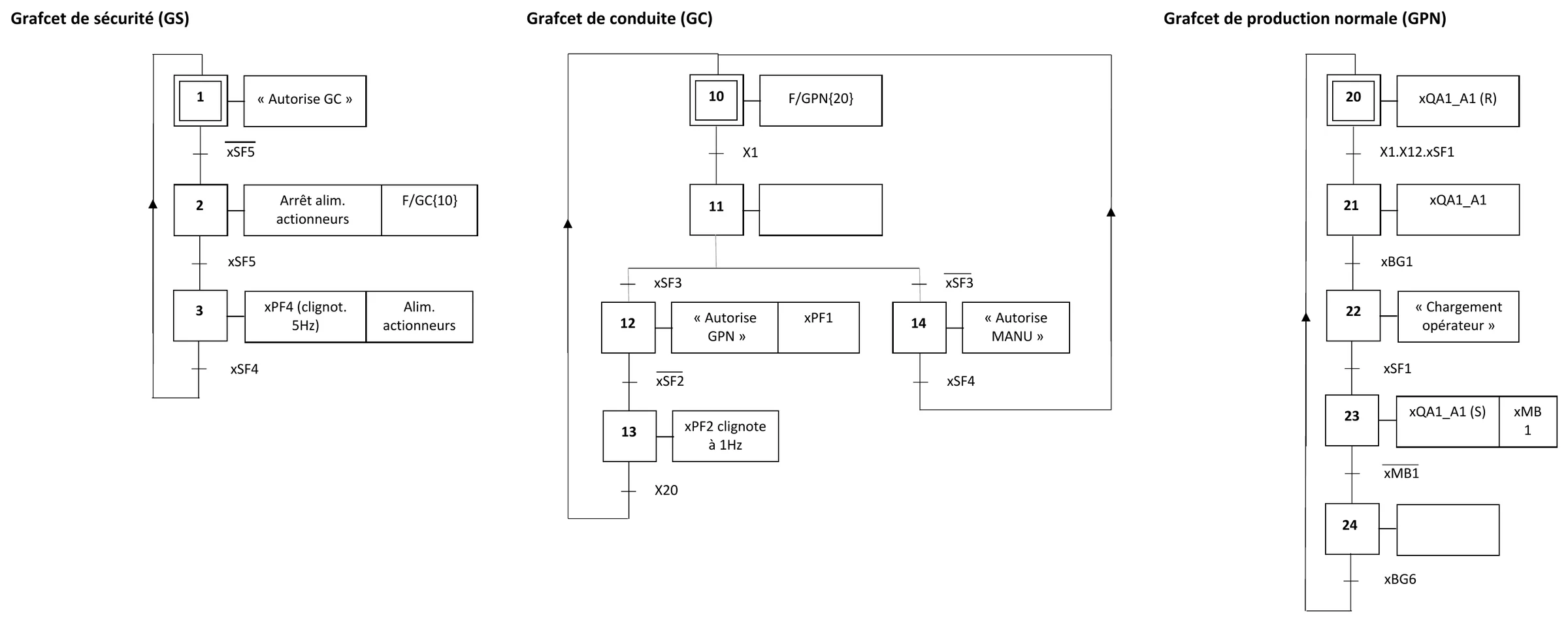
- Three GRAFCET layers: safety (GS) governs conduct (GC), which enables normal production (GPN) or manual mode.
- Automatic: a single press on Start runs production continuously, provided the initial conditions are met.
- Switching to manual, or pressing Stop, lets the current cycle finish — up to the pallet leaving the station — before the mode changes.
- Emergency stop: power to every actuator is cut and the arm freezes where it is. After release, Reset returns the station to its initial conditions and the operator takes back any part left in the gripper.
- Initial conditions: slots 7–12 full, 1–6 empty, arm homed and retracted, conveyor stopped.
Stock management
The station manages its 12-slot store on its own: it always knows which slots are free or occupied and chooses the slot to load or unload. When the store is full or empty, an alarm is shown on every HMI screen and production stops until the operator steps in and presses Reset.
HMI screens
| Screen | Content | Access |
|---|---|---|
| Home | Log in / log out, name of the connected user | Operator · Maintenance |
| States | X and Z encoder values, Y extended / retracted, I/O of the module | Operator · Maintenance |
| Scenarios | Load / unload selection and validation, slot number, store fill level | Maintenance |
Maintenance sessions close automatically after 5 minutes; the store full / empty alarm is visible whatever the screen.
Method & deliverables
- V-cycle with five reviews: preliminary design, detailed design, maintenance, end of verification and installation.
- Every requirement written to be verifiable and checked against a test sheet in the verification file.
- Work packages from homing and normal production to conduct, safety, HMI and two integration phases, within a 44-hour budget.
- Maintenance file in English: fault localisation, replacement procedures, and a spare-parts stock sized from MTBF figures for a 25-year life at 16 h a day, 5 days a week.
- Installation file and certificate of conformity; every deliverable versioned with a CRC32 fingerprint.